

This is an illustration from the Great Exhibition, 1876, or The great Centennial exhibition critically described and illustrated, by Phillip T. Sandhurst, which you can leaf through over on archive.org.
Here’s how this machine, part of the “Machinery Hall” chapter, is described:
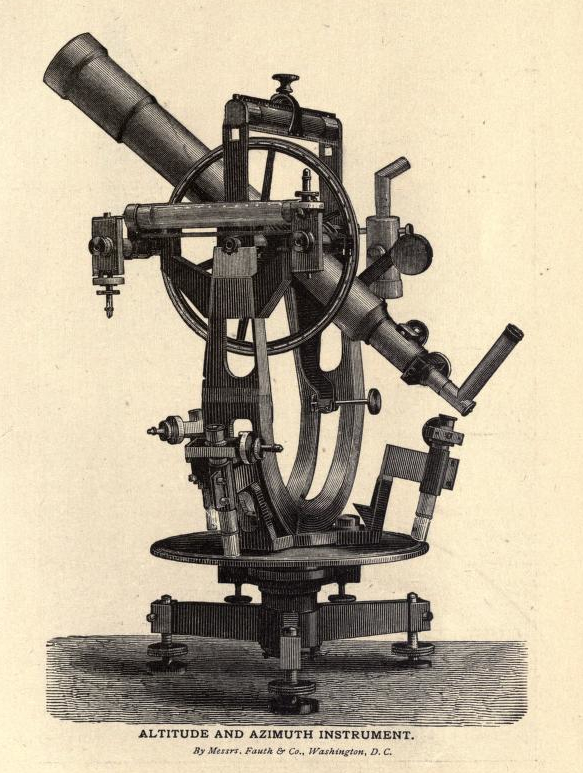
We have mentioned before the fine exhibit of astronomical instruments made by Messrs. Fauth & Co., of Washington, D. C, and we refer to this exhibit again to call attention to an exceedingly perfect Altitude and Azimuth Instrument which has been purchased by the United States Coast Survey Department for triangulation and determination of azimuth. The altitude of a star or other body is its height above the horizon expressed in degrees, the greatest altitude of course being ninety degrees. The azimuth is the angle made by the meridian and the vertical circle in which a heavenly body is situated, and is measured along the horizon for the north or south towards the west, according as the north or south pole is elevated above the horizon, to the point where a circle passing through the zenith and the body cuts the horizon. The instrument of which we speak, and which is represented by the engraving on page 483, from the nature of its construction is employed in the measurement of vertical and horizontal angles, and may be used as transit for time observation, also for double zenith distances for latitude, and will determine the astronomical position of any station. For geodetic purposes it is used in primary triangulation to measure the angles with the utmost precision. It has two graduated circles and a telescope, the planes of the circles being at right angles to each other, one called the azimuth circle being connected with a solid support, on which it is leveled and kept in a horizontal position, and the other called the altitude circle, which is mounted on a horizontal axis, which also carries the telescope like a transit. The design and construction of the instrument are quite novel, combining all the advantages of a repeating instrument without its defects. The horizontal limit, which is thirteen inches in diameter, is graduated to five minutes, and may be read off by means of three microscopes at different points to the nearest single second, these microscopes being illuminated by prisms which derive their light from overhead, and are effective for any position of the circle. This circle may be shifted if desired, so as to bring different parts of the graduation under the microscopes, and thereby eliminate any error or eccentricity in division. The vertical circle is ten inches in diameter, and is graduated the same as the horizontal circle, but is read by two microscopes, a very sensitive level reading to single seconds of arc being affixed to the microscopes to note any deviation from the vertical. This circle may also be shifted for position. Both circles are entirely free from clamps, these being attached to the centre, thereby avoiding the great risk of strain. The clamps and slow motion have differential screws. For time observation a striding level of the utmost perfection is supplied, which is set over the hard pivots of the telescope axis, so as to note any deviation from the meridian, the level being ground to a radius of about two thousand feet, each division of its graduation representing a second of arc. Both this and the level over the microscopes of the vertical circle have air-chambers to correct the bubbles for changes of temperature.
So now you know how to operate it, mostly. There’s a bit more on the operation of the telescope component, but… you get the idea.